


You want to create a part that not only looks good but is also strong enough and easy to print without any hassle. In this guide, I'll walk you through designing 3D models for 3D printing step by step.
The focus is on FDM, the most common technique where molten plastic is built up layer by layer. You'll learn how to design smartly, what to keep in mind, and how to prevent errors.
What is a 3D model and what does it mean for printing?
Simply put, a 3D model is the digital blueprint of your part. A printer can't do anything with it until you convert it into layers. Because an FDM printer works layer by layer, your design choices will determine how strong, accurate, and clean the final result is. Think about layer orientation, visible surfaces, and the areas where your part needs to withstand stress.
CAD and STL: the two most important file formats
A CAD file is your design file. Here, you can still change everything: adjust dimensions, add features, and improve shapes. As soon as you export to STL you convert those perfect mathematical shapes into a mosaic of triangles. That's fine for the printer, but almost impossible to edit further. In short: CAD is flexible and adjustable, STL is the finalized version you print.
Anisotropy: why direction matters
FDM prints are anisotropic. This means they are stronger in one direction than another. In the XY direction (width and depth), a part is usually sturdier, while in the Z direction (height), it can break more easily along the layers. That's why it's smart to orient parts so that the main forces fall within the XY plane. It's better to round off internal corners so that stress doesn't accumulate and cracks don't form.
Essential design rules for FDM
Good design starts with simple rules of thumb. You don't have to be an engineer, but you do need to know how to balance wall thickness, overhangs, and fits.
Wall thickness and strength
You should always determine wall thickness in relation to your nozzleFor a standard 0.4 mm nozzle, a minimum wall thickness of 0.8–1.2 mm works for non-critical parts. For functional parts, it's better to use 1.6–2.4 mm to ensure there is enough strength in the load-bearing areas.
Walls that are too thin can delaminate: the layers won't bond properly and will come apart. Printing too solidly adds little extra strength but increases the risk of shrinkage and adds to print time.
Overhangs, holes, and tolerances
Overhangs are surfaces that stick out without support. Anything steeper than about 45 degrees requires support. This makes the surface rougher and the print more expensive. You can avoid this by angling surfaces or shortening bridges. The less support you use, the cleaner the result.
Holes and fits always require some clearance. Model holes slightly larger than the nominal size, as they often shrink a bit in FDM. For sliding parts, allow for a few tenths of a millimeter on each side.
This is even more important for snap-fit joints. A snap-fit is a design where a flexible arm clicks into a recess, holding two parts together without screws or glue. To prevent breakage, make the arms tapered and round off the transition to the base.
The best software for creating 3D models
The choice of software depends on your goal, your experience, and how often you plan to design. The great thing is that there is a suitable package for every level and application.
For beginners and simple designs
Tinkercad is simple and works directly in your browser. It’s ideal for beginners and simple parts like holders, caps, and clips. You’ll quickly learn to think in volumes and get a feel for 3D design.
For advanced users and technical models
Autodesk Fusion 360 is more powerful and parametric. This means you can set relationships between dimensions and easily create variations. For technical parts and functional prototypes, this is the most logical choice.
Blender on the other hand, is interesting for organic shapes and creative designs. It requires a bit more discipline to maintain tight tolerances, but it offers a lot of freedom for fluid shapes.
Other good options
If you prefer working in a browser or using open-source software, then Onshape and FreeCAD great alternatives. Onshape is modern, runs entirely in your browser, and offers features similar to commercial CAD packages. FreeCAD is free and versatile; while its interface can be a bit less intuitive, it is constantly evolving and has a growing community.
How to export and check your model before printing
Your model is finished in CAD, but that doesn't mean it's ready to print without issues. Many errors occur during the export or mesh-checking process. By paying a little extra attention here, you'll save yourself a lot of failed prints.
STL quality and file size
When you export a model to STL format, the software converts your smooth surfaces into triangles. The finer these triangles, the smoother curves will look in the slicer. However, the finer your export, the larger your file.
An export that is too coarse results in jagged edges, while an extremely fine export just creates massive files that are slow to work with. The goal is to find a balance: fine enough that curves look smooth, but no heavier than necessary.
Checking scale and mesh
Always work in millimeters and check in the slicer to ensure the scale is correct. Incorrect units are a common mistake that can cause parts to end up ten times too small or way too large.
Additionally, your model must be manifold. This means the mesh is completely closed, with no holes or overlapping faces. A mesh that isn't watertight can cause strange print paths. Most slicers have built-in repair features, but it's better to fix this during the export process.
Common mistakes when designing for 3D printing
Everyone makes mistakes when designing, especially at the beginning. The good news is that many problems are predictable and preventable.
Walls that are too thin and holes that are too small
A common issue is modeling walls that are too thin. They look fine in CAD, but in practice, those walls don't have enough layers to be sturdy. The result: delamination or breakage.
The same applies to holes. With FDM printing, they often close up slightly, meaning screws and pins won't fit. Adding a few tenths of a millimeter makes a world of difference.
Unnecessary support and solid modeling
Support is useful, but avoid it as much as possible for better prints. If you design a part with steep overhangs, you can be sure it will require support. By cleverly tilting surfaces or repositioning details, printing becomes much easier.
Solid models are another pitfall. They might seem stronger, but solid prints tend to warp and consume a huge amount of time and material. Smart ribbing and hollow shapes are often stronger and lighter.
How to make your design printable and affordable
A good design isn't just technically sound; it's also cost-effective and efficient to print. You have a lot of control over the price by modeling smartly.
Limit height and build volume
Every extra millimeter in height adds to print time. It’s better to lay long, narrow parts flat if the structural integrity allows it. For extremely long parts, split them into segments and design them with snap-fit or screw connections so they can be assembled later.
Be smart with material and support
Stiffness doesn't come from making everything solid, but from using the shape to your advantage. Ribs, hollow profiles, and extra outer layers are more effective than high infill. For most applications, 15 to 30 percent infill with enough perimeters works perfectly. At the same time, you save a lot of material and print time.
You can also often avoid support by angling corners or repositioning details. Every hour of print time saved shows up directly in the price-to-quality ratio. For more tips, check out our article on cheaper 3D prints.
Frequently asked design questions
Many design questions come up time and again. By keeping these in mind from the start, you can avoid disappointment.
How small can text be on an FDM print?
Text should be at least 0.6 to 0.8 millimeters high or deep, with a line thickness of at least 0.4 millimeters. Orient the text facing upward for the best results.
Can you print hinges and snap-fit joints?
Yes, you can. A snap-fit joint is a flexible construction where a small arm clicks into a recess to secure parts. Always include tolerance and round off sharp corners. For hinges, it’s important to build in enough clearance so the parts move smoothly.
How do you prevent corners from warping?
Warping mainly happens with larger parts and materials like ABS of ASA. Rounded corners, a brim in the slicer, and using the right material make a big difference. If you're printing for outdoor use, ASA is usually the safest bet.
Conclusion and next steps
Good 3D print design doesn't start at the printer; it starts with your model. If you keep wall thickness, overhangs, tolerances, and orientation in mind, you'll get parts that are strong, look great, and come off the printer without any surprises.
Small tweaks like rounding a corner or adding a few tenths of a millimeter of extra clearance often make the difference between a perfect fit and a failed one.
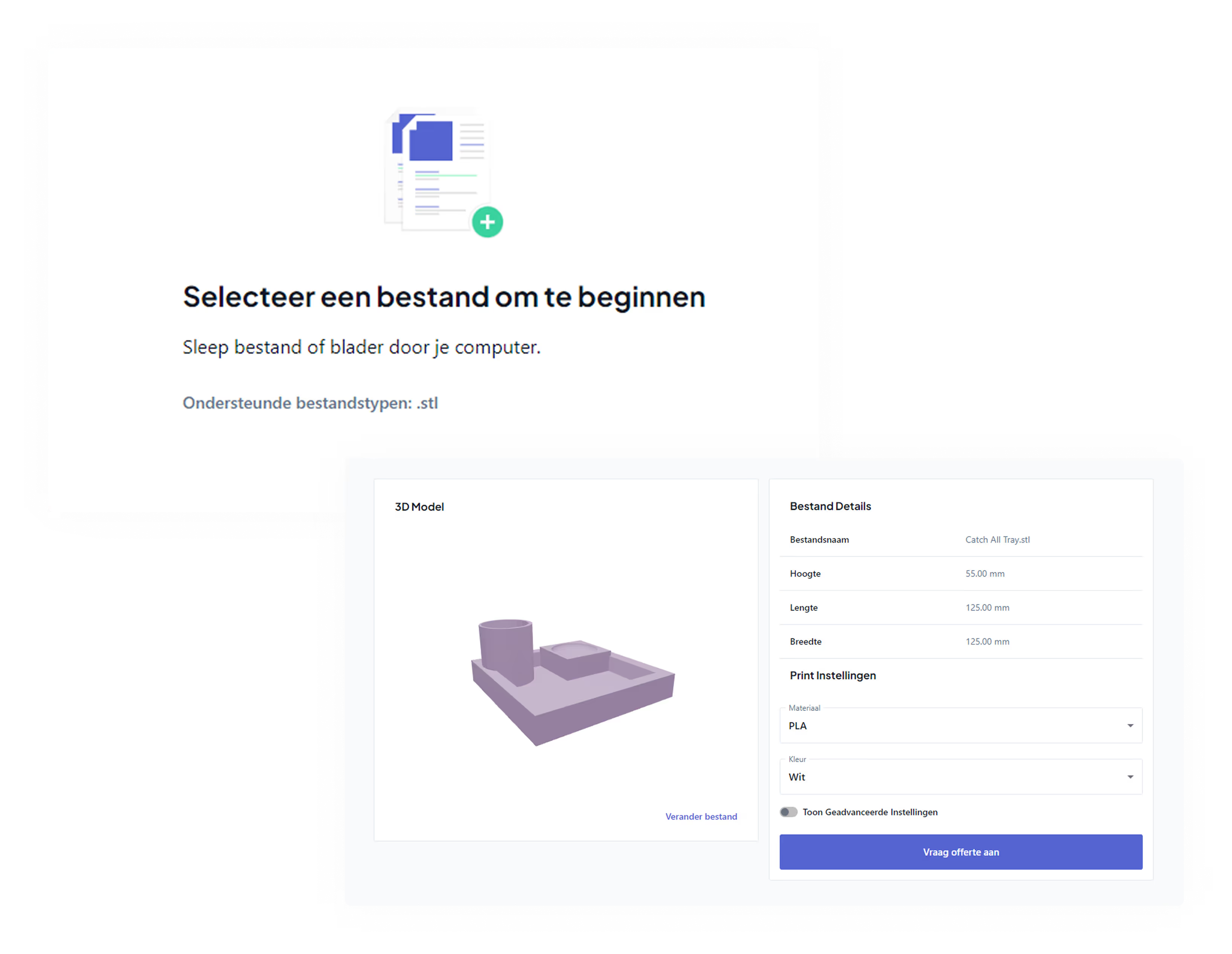
Want to hold your design in your hands right away without wrestling with settings or test prints? Upload your model and see the price instantly.